|
||||
| News and Information about the Test of Electronics in Research & Design, Production, Maintenance, and Installation. | ||||

Main MenuNewsletterNews AreaInfo AreaWeblinksProduct Focus |

Readers Top 5 News of last 30 days
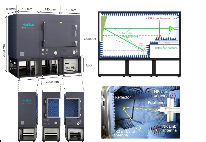
Latest Test and Measurement NewsBackground: 5G-NR Over-The-Air (OTA) Test ChallengesIntroducing Over-The-Air (OTA) measurements in the validation of 5G chipsets and user equipment (UE) poses numerous new obstacles in meeting regulatory requirements and achieving the desired measurement accuracy. This article presents some of the main challenges of 5G-NR OTA testing, along with new methods developed to overcome them. These novel test solutions help to reduce time to market, lower cost-of-test and give companies a competitive advantage in the new frontier of wireless. 5G aims at offering enhanced mobile broadband (eMBB), with data rates as high as 20 Gbps. To boost capacity through the adoption of wider contiguous bandwidths, the focus has shifted to higher frequencies, namely millimetre Waves (mmW). Device designs optimized for Frequency Range 2 (FR2) are highly complex and present challenges, including high path loss, IQ impairments, phase noise, linear/non-linear compression, and frequency error, which are more common with higher frequencies and wider bandwidths. To mitigate the impact of high path-loss in FR2 (> 60 dB), beamforming techniques have been developed, realized through active antenna arrays (AAS) with multiple phase steered antennas and high-speed signalling techniques. In AAS, the transceiver frontends are integrated together with the antenna array. In other words, no traditional RF output ports are available, so no cable connection is possible. OTA testing has become the default 5G test case, at least for FR2. This affects test procedures and demands the achievement of the measurement uncertainty requirements in an OTA environment. Another important obstacle to overcome for effective device verification is coping with the tighter specifications associated with the key test metrics. OTA Test methods In TS 38.810, 3GPP defines three permitted OTA UE test methods: Direct Far Field (DFF), Indirect Far Field (IFF) and Near-Field-To-Far-Field (NFTF). Determining the best one for an application depends on several factors, including the antenna size and configuration of the Device Under Test (DUT). DFF consists of dimensioning the chamber so that the test antenna and the DUT are at a distance greater than 2D2/ λ, where D is the largest device size and λ is the wavelength. This distance increases with the antenna size D and with frequency. When D is large and/or the frequency is high, the DFF approach leads to chambers that are both impractically large and prohibitively expensive. Very often the device is in its own casing during the test, therefore the exact DUT antenna size and/or location are unknown. The largest device size should be used in these cases, leading to very large chambers even for relatively small devices. For these cases, there are more practical ways to create far-field distance testing conditions. IFF methods allow the creation of far-field conditions within reduced chamber sizes. While offering a smaller footprint and lower path-losses than DFF, IFF methods still offer a reasonable speed of test, supporting RF parametric measurements to characterize beam-patterns and validate beam-steering, EIRP/TRP and EIS testing, and beamforming validation. The main drawback of IFF methods is that they are limited to measuring a single Angle of Arrival (AoA), so they can’t support some RRM test cases, nor the beam management tests. The most common IFF setup is called Compact Antenna Test Range (CATR), which uses a parabolic reflector to transform a spherical wave into a plane wave. Figure 1 shows MA8172A CATR for FR2 5G-NR OTA testing of UEs.
Figure 1. MA8172A CATR for FR2 5G-NR OTA Testing of UEs.
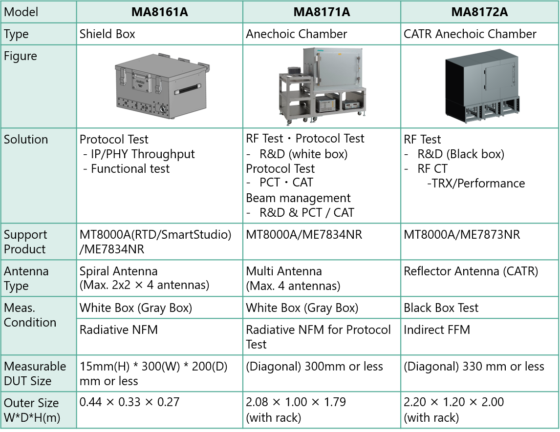
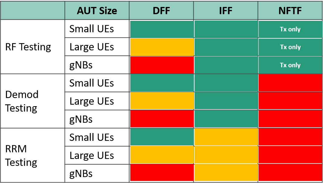
Choosing the right OTA method Evaluation and qualification are required throughout the UE development process, from R&D to mass production and certification. Test requirements vary across different stages, so no single OTA test method can be regarded as the best for characterizing 5G FR2 devices. Engineers could choose the optimal OTA method based on various factors, including test interface, metrics and test requirements of different phases, cost of the test setup involved and trade-offs between measurement uncertainties and test time. Figure 2 shows an overview of different OTA chamber solutions that satisfy a variety of test needs. The best solution depends on several aspects, such as DUT size and weight, and the need for spherical or non-spherical testing. As a reference, Table 1 includes a high-level summary of the fidelity and applicability of the DFF and IFF OTA test environments.
Figure 2. Overview of different 5G OTA chamber solutions that satisfy a variety of test needs.
Table 1. High-level summary of fidelity and applicability of 5G OTA test environments. Color legend: Green=Full Applicability; Orange=Applicable with restrictions; Red=Not Applicable.
OTA Test Challenges To ensure accuracy, reliability, and efficiency of OTA tests, the following technical challenges must be properly addressed.
1. Test Time Factors Test time is a critical factor in 5G OTA testing. As engineers conduct OTA tests using the grids specified by 3GPP, they may realize that the measurement accuracy needs improvement. Statistically, the finer the sampling grid, the smaller the measurement uncertainty. However, the test time increases with finer grids. Let’s use total radiated power (TRP) as an example. TRP is necessary to ensure that a radio is transmitting power in accordance with regulatory compliance. With side lobes and back lobes, the only way to measure the TRP is to integrate the power in a 360° sphere around the entire antenna, which adds time to the measurement. The TRP OTA testing time is determined by the moving time of the positioner, by the number of points and by the fact that both horizontal and vertical polarization must be considered. It is critical that commercially available solutions take this aspect into account. Anritsu’s MX800010A solution, based on the Radio Communication Test Station MT8000A, reduces test time by using two RF converters along with a constant density algorithm approach.
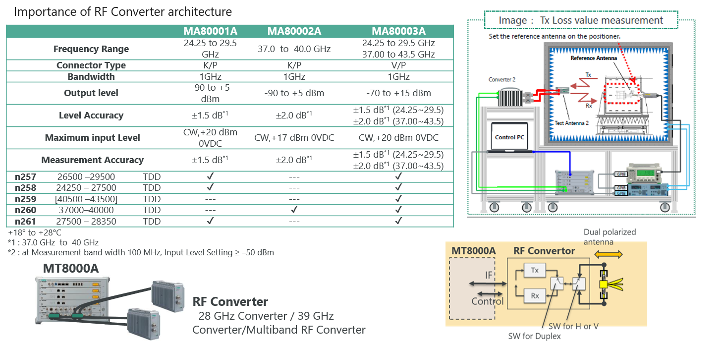
2. Calibration Another challenge in 5G OTA testing is overcoming the significant path loss, which can easily be >50 dB. An accurate setup calibration is necessary to properly measure the DUT RF metrics of interest. It is typically done using a reference antenna with known gain values. To perform the calibration, a reference antenna is placed in the centre of the quiet zone, a volume within the chamber in which measurements are made and a DUT is illuminated with nearly uniform amplitude and phase. Typical quiet zone specifications are 10 degrees of phase variation, ± 0.5 dB of amplitude ripple, and 1 dB of amplitude taper. mmW modules allow generating and receiving mmW signals by converting them from baseband to mmW from and to the test equipment (i.e. network simulators). They can help minimize path-losses and improve calibration accuracy. Due to the higher path losses at mmWaves, it is important to place the converters as close as possible to the antennas. Figure 3 shows the Anritsu MA8000XA RF converters. They can be positioned right next to the feed antennas without the need for any Common Interface Unit (CIU), therefore minimizing path losses. On the rear panel, they are connected to the base RF module of the MT8000A Radio Communication Test Station using an IF signal path, allowing the available measurement dynamic range to be optimized. This architecture ensures that losses are minimized, leading to a higher SNR, lower measurement uncertainty and more accurate results.
Figure 3. Anritsu MA8000XA RF converters for mmW FR measurements, designed to minimize path-loss and improve OTA calibration accuracy.
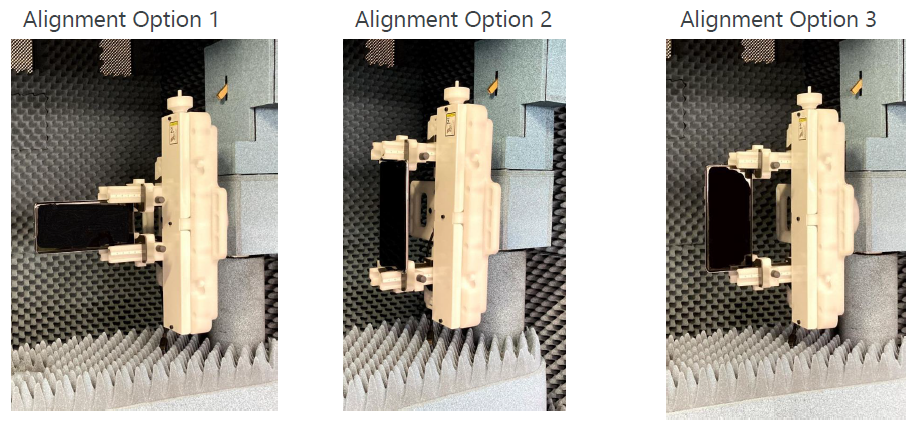
3. DUT Alignment mmW antennas are highly directional, requiring the mechanical alignment to be very precise. To ensure repeatable placement of the DUT, custom milled holders are required to reliably return the DUT to the expected location. Accurate and reproducible results can only be obtained if the best alignment option can be selected to match the terminal design and antenna position. Anritsu has recently introduced the DUT Holder MA8179A-AK011, designed using low loss material to prevent disturbing measurements and to meet all these requirements in a single product, facilitating the introduction of mmW terminals to the market. The MA8179A-AK011 is a compact jig mounted on the positioner to align the test terminal in the correct position. This allows the Anritsu CATR MA8172A chamber to support the DUT, like a smartphone or a tablet, in the positions and orientations specified by the 3GPP Alignment Option 1/2/3. Additionally, it satisfies both the quality of Quiet Zone recommendation for the 3GPP RF/RRM Conformance Test, as well as simplifying test-terminal mounting/dismounting in the test chamber compared to earlier jig designs. The accuracy of the mounting ensures that measurements and positions can be readily reproduced.
Figure 4. Anritsu MA8179A-AK011 DUT Holder, supporting the DUT in the positions and orientations specified by the 3GPP Alignment Option 1/2/3.
4. Extreme Temperature Condition In TS38.101-2, 3GPP defines the temperature range “-10 °C to +55 °C” as Extreme Temperature Condition (ETC). Power and sensitivity are required, so RF testing in the 3GPP also covers extreme environmental testing (hot/cold). Anritsu has recently launched its Temperature Testing Option MA8172A-010, to upgrade the CATR Anechoic Chamber MA8172A. This facilitates previously difficult temperature tests for 5G mmW cell phones. Used in combination with the Radio Communication Test Station MT8000A for 5G R&D applications and the New Radio RF Conformance Test System ME7873NR for 5G conformance tests, the RF characteristics of 5G mmW cell-phones can be confirmed in a controlled temperature environment to help assure and improve cell-phone quality. In addition, continuous testing at low, normal, and high temperatures is not only linked with improved test efficiency but also plays a key role in the growing mmW market.
Conclusion OTA measurement is mandatory to evaluate the performance of 5G mmW devices. It poses numerous challenges in achieving the desired measurement accuracy for the validation and conformance processes. This article presented an overview of the challenges, solutions, and best practices in OTA testing. No single OTA method can be determined as the unique solution to characterizing 5G mm-Wave devices comprehensively. The optimal choice is based on trade-offs between different performance metrics to be evaluated, measurement accuracy, cost-effectiveness, complexity of different test environments, repeatability in a controlled environment, etc. Choosing the best test solution helps to reduce time to market, lower cost-of-test and gives a competitive advantage in the new frontier of wireless. Partnering with a test manufacturer with experience in each element of the OTA environment will help meet RF, demodulation, and functional test requirements. Unnecessary rework, which can lead to delayed time-to-market and additional design costs, will be avoided as a result. Author: Enrico Brinciotti, PhD, Field Application Engineer, Anritsu www.anritsu.com/ Related Articles: |

Upcoming Events More events...
Tag CloudOscilloscope
JTAG
Boundary Scan
Goepel
PXI
Rohde & Schwarz
Tektronix
Keysight
AOI
Anritsu
National Instruments
Inspection
Teledyne LeCroy
Aeroflex
LTE
Yokogawa
AXI
Spectrum Analyzer
Keithley
In-Circuit-Test
Signal Analyzer
Automotive
EMC-Test
Signal Generator
Advantest
Multitest
B&K Precision
Corelis
Power Supply
SPI
Flying Prober
Teseq
Cognex
Switching
Teradyne
Viscom
Pickering
Fluke
GAO Tek
PCIe
|
||
|
© All about Test 2018 |
||||
 How to resolve AdBlock issue?